
- pressure rating PN 10
- min. flow velocity 0.2 m/s
- max. flow velocity 2.5 m/s
- min. operating temperature 0 °C
- max. operating temperature 100 °C
- protection class IP65
- power supply 8…33 V DC
Menu


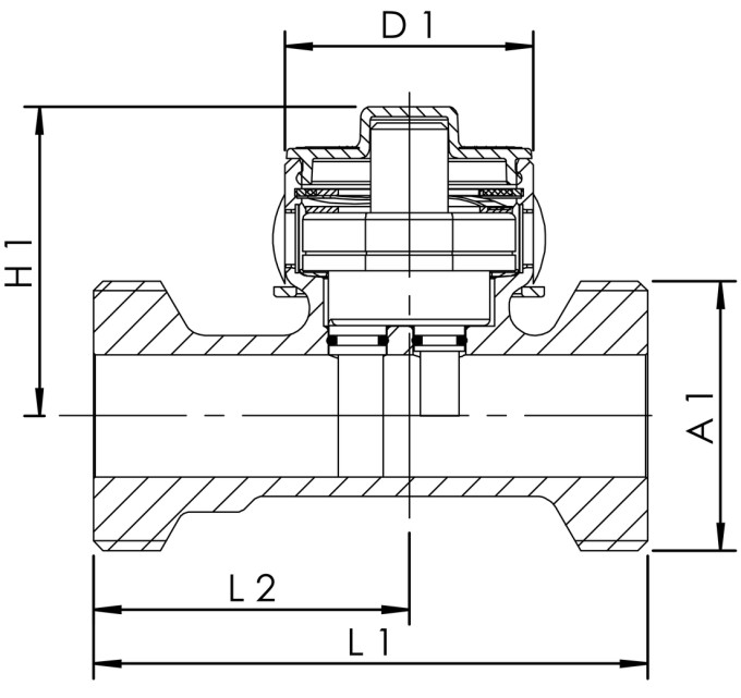
| Part no. | DN | A1 | D1 (mm) |
H1 (mm) |
L1 (mm) |
L2 (mm) |
pressure loss at 1 m/s (hPa) |
pressure loss at 2 m/s (hPa) |
cv (m³/h) |
Weight (kg) |
|---|---|---|---|---|---|---|---|---|---|---|
| 1386G01000 | 10 | G 3/4 | 38.5 | 46 | 65 | 35 | 114 | 460 | 1.9 | 0.36 |
| 1386G01500 | 15 | G 3/4 | 38.5 | 44 | 65 | 32 | 36 | 142 | 3.3 | 0.35 |
| 1386G02000 | 20 | G 1 | 38.5 | 46 | 75 | 40 | 28 | 109 | 6.8 | 0.31 |
| 1386G02500 | 25 | G 1 1/4 | 38.5 | 48 | 86 | 49 | 25 | 100 | 11.2 | 0.57 |
| 1386G03200 | 32 | G 1 1/2 | 38.5 | 50.5 | 109 | 70 | 32 | 124 | 16.3 | 0.74 |
| 1386G04000 | 40 | G 1 3/4 | 38.5 | 57.5 | 109 | 66.5 | 30 | 121 | 26 | 0.94 |
| 1386G05000 | 50 | G 2 3/8 | 38.5 | 64.5 | 113 | 70 | 31 | 123 | 40.3 | 1.37 |
| Part no. | DN | CAD model | Characteristic curve |
|---|---|---|---|
| 1386G01000 | 10 | Show 3D data | Show characteristic curve |
| 1386G01500 | 15 | Show 3D data | Show characteristic curve |
| 1386G02000 | 20 | Show 3D data | Show characteristic curve |
| 1386G02500 | 25 | Show 3D data | Show characteristic curve |
| 1386G03200 | 32 | Show 3D data | Show characteristic curve |
| 1386G04000 | 40 | Show 3D data | Show characteristic curve |
| 1386G05000 | 50 | Show 3D data | Show characteristic curve |


